Single vs Multi Channel Seismic Surveys

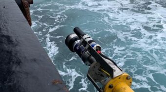
At its most basic level, a hydrophone is an underwater microphone capable of detecting subsea sound and converting it into electrical energy so that it may be amplified, transmitted and recorded. Most devices are made from a special ceramic material that produces a piezoelectric voltage when subjected to pressure changes from sound travelling through the water.
Hydrophones in geophysical surveys
In the marine geophysical survey industry, hydrophones are commonly used in conjunction with a seismic sound source to perform seismic reflectivity surveys. These surveys provide vital information for companies searching for oil, natural gas, and minerals or those planning offshore construction projects, such as wind farms.
Seismic reflectivity surveys work in a similar way to sonar, radar and other reflective detection/ranging methods. They utilise a pressure wave from an acoustic or seismic energy source, which travels down through the water column and into the seabed and subsequent layers of soil/geology. Where this pressure wave meets boundaries between distinctly different geological layers, some of the downward travelling pressure wave is reflected back up to the surface. By recording these reflected returns with a pressure-sensitive hydrophone array, the reflected sound/pressure can be amplified, recorded and used to build a structural image or profile of the geology beneath the seabed.
Reflectivity surveys are the most commonly employed seismic survey method and, hence, are typically referred to in the geophysical survey industry as simply a seismic survey or Sub-Bottom Profiling (SBP). Strictly speaking, the correct name will depend on the frequency of the seismic source being used. Sources with frequency content above 1kHz are referred to as SBP surveys and those below 1kHz are seismic surveys. Our Guide to Sub-bottom Profiling provides greater detail on this.
What makes a good hydrophone?
A good hydrophone is one that:
- is sensitive to low-amplitude sounds
- can detect sounds over a broad frequency spectrum
- amplifies as much useful coherent signal (that is, reflected from the subsurface geology) as possible while minimising the impact of random noise from environmental and electronic sources (referred to as the signal-to-noise ratio)
Geophysicists commonly employ two alternative survey configurations to achieve this in a marine reflectivity survey: ‘Single Channel Seismic’ (SCS) and ‘Multi-Channel Seismic’ (MCS). Both of these configurations aim to improve sensitivity and the signal-to-noise ratio by combining the output of multiple individual hydrophone elements. This improves sensitivity by a factor of N (where N=number of elements) and improves the signal-to-noise ratio by a factor of √N.
However the way this is achieved by each method is quite different.
Single Channel Seismic (SCS) overview
A single channel survey is named for the single channel hydrophone used in this type of survey. This single-channel hydrophone actually consists of multiple hydrophone elements wired together in parallel to form a single group or array’ This array is then housed in a single plastic tube, which is usually filled with a silicone fluid or gel. During survey acquisition the electrical signal or response from each individual element is combined electronically and the output is recorded as one single channel (hence the name).
The image below shows the equipment configuration for a typical SCS survey. The seismic source and hydrophone are deployed in a ‘transverse’ configuration (source receiver side-by-side), the image below that, shows a ‘longitudinal’ configuration (source in front of the hydrophone in the direction of tow). Both these configurations are acceptable, but a transverse typically yields the best results in shallow water surveys; due to a reduction in phase variation between elements.
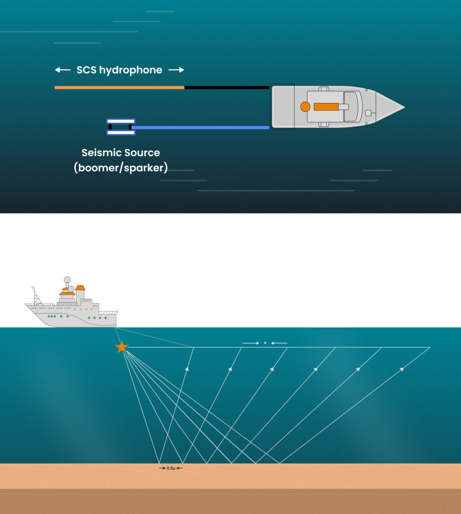
Whichever configuration is used in the survey, the acquisition sequence will be the same. A survey vessel will move along a pre-defined survey line, towing the seismic source and hydrophone behind the vessel and periodically firing the source.
The geometry of reflectivity survey means that each time the source is fired, the hydrophone samples the seabed and subsurface reflections from a location halfway between source and hydrophone over an area half the size of the SCS array length.
Once a survey line has been completed the data recorded at each shot location can be plotted together to produce a seismic profile.
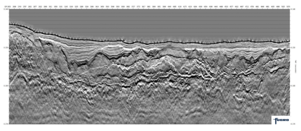
Compared to a MCS, the geometry and mode of acquisition of SCS is very simple, comparatively cheap and can provide good sub-surface profiles with very little need for data processing and technical know-how. For this reason a SCS survey makes a great choice for ‘first pass’ surveys in new areas where little is known about the seabed and geology below. The knowledge gained from this first pass survey can then be used to focus further geophysical or geotechnical surveys that may be needed, keeping costs to a minimum.
Multi-Channel Survey (MCS) overview
With a MCS survey, although the method of data acquisition is identical to a SCS survey, the way in which data recorded from each hydrophone, then subsequently processed is crucially different.
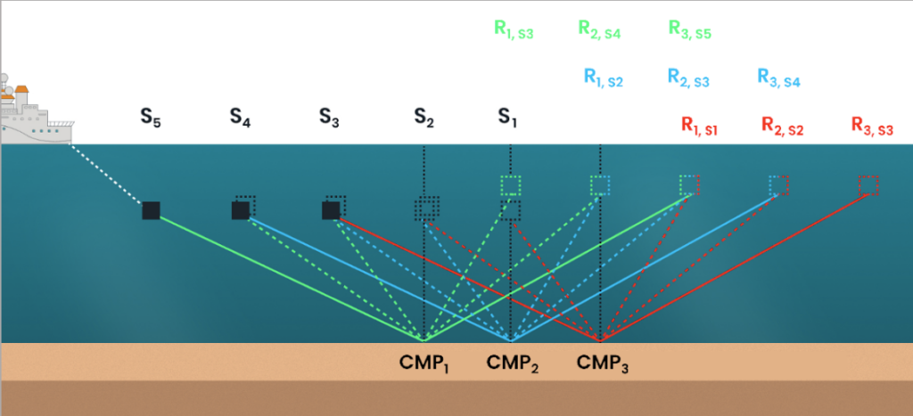
With a multi-channel streamer the electrical response of individual hydrophone elements OR small groups of elements are recorded separately and each separate recording is referred to as a channel; hence ‘multi-channel streamer’. A multi-channel streamer will typically be far longer than a single channel streamer and have its channels evenly spaced out along its length. For high-resolution MCS surveys, streamers with 16-96 channels, and intervals of 1m, 1.56m and 3.125m are common.
As discussed in the previous section, for every shot in a seismic survey we are sampling reflected seismic data from a ‘mid-point’ halfway between the source location (Sx) and the element/channel location (Rx). The key objective of a MCS survey is to acquire the data in such a way that each channel of the streamer records a different shot on the survey line, with a shared ‘common mid-point’ (CMP). In practice, this is done by firing the seismic source at an interval corresponding to half the channel spacing. The figure below shows visually how this works.

The geometry of a MCS gives it a number of advantages over SCS:
Improved data quality:
Signal to noise ratio is improved because, not only are recordings from different receivers combined, but also different shots.
More channels are possible: for a single channel survey the maximum length of the array is limited by water depth (shallow water requires shorter arrays). However, with the multi-channel set-up this is not the case and the array length and number of channels are not limited.
Improved data accuracy:
For both the SCS and MCS, the CMP location will have a footprint equal to half the length of the array. In SCS arrays are typically a few meters long. However, for a MCS array lengths can be much shorter; down to a few centimetres where the channel group is made up of a single element.
More processing options and a larger weather window:
Processing and enhancement of seismic data is possible through a wide range of well-established and highly developed software packages and processing companies. Although processing methods can be applied to both SCS and MCS, MCS data provided far more enhancement options. Advanced MCS data processing can lead to significant improvement in data recorded even in poor weather conditions, reducing survey operation times.
Capacity to acquire 3D data:
Multi-channel data can be acquired using multiple, simultaneously deployed, parallel streamers and sources. This gives the option to produce highly detailed 3D volumes (models) of the subsurface, rather than 2D slices.
Although these 3D volumes offer a great improvement in survey coverage and detail, they also require a larger investment in terms of equipment, expertise and processing know-how.
What are the applications of Multi-Channel Survey?
Sparker/Boomer source MCS can provide highly accurate, high-resolution data for the first 100m or so below the seabed, providing geoscientists and engineers with a valuable tool to understand local geology or to identify potential geohazards. This data is essential for offshore projects such as wind farms, where the knowledge is needed to safely carry out pylon installations and cable trenching operations.
Choosing aae equipment and our range
applied acoustics has a large range of sub-bottom profiling and seismic equipment Sparkers, CSP Units, Hydrophones and MiniPods.
We are now pleased to announce the launch of HydraSeis: our first multi-channel seismic acquisition system, designed to complement our existing range of UHR sound source and provide a step change in performance and data quality.