Category: Sub-bottom profiling
At its most basic level, a hydrophone is an underwater microphone, capable of detecting subsea sound and converting it into electrical energy so that it may be amplified, transmitted and recorded. Most devices are made from a special ceramic material that produces a piezoelectric voltage, when subjected to the pressure changes; resulting from sound travelling through the water.
Hydrophones in geophysical surveys
In the marine geophysical survey industry, hydrophones are commonly used in conjunction with a seismic sound source to perform ‘seismic reflectivity surveys’. These surveys provide vital information for companies searching for oil, natural gas, minerals or for those planning offshore construction projects, such as wind farms.
Essentially, seismic reflectivity surveys work in a similar way to sonar, radar and other reflective detection/ranging methods. They utilise a pressure wave from an ‘acoustic or seismic’ energy source, which travels down through the water column and into the seabed and subsequent layers of soil/geology. Where this pressure wave meets boundaries between distinctly different geological layers, some of the downward travelling pressure wave is reflected back up to the surface. By recording these reflected returns, with a pressure-sensitive hydrophone array, the reflected sound/pressure can be amplified, recorded and used to build a structural image or ‘profile’ of the geology beneath the seabed.
Reflectivity surveys are probably the most commonly employed seismic survey method, and hence are typically referred to in the geophysical survey industry as simply a ‘seismic survey’ or ‘Sub-Bottom Profiling’ (SBP). Strictly speaking, the correct name will depend on the frequency of the seismic source being used. Sources with frequency content above 1kHz are referred to as SBP surveys and below 1kHz as seismic surveys. Our Guide to Sub-bottom Profiling provides greater detail on this.
What makes a good hydrophone?
A good hydrophone is one that:
- is sensitive to low-amplitude sounds
- can detect sounds over a broad frequency spectrum
- amplifies as much useful ‘coherent’ signal (that is, reflected from the subsurface geology) as possible, while minimising the impact of ‘random noise’ from environmental and electronic sources (referred to as the signal-to-noise ratio)
To achieve this in a marine reflectivity survey, two alternative survey configurations are commonly employed by geophysicists: ‘Single Channel Seismic’ (SCS) and ‘Multi-Channel Seismic’ (MCS). Both of these configurations aim to improve sensitivity and the signal-to-noise ratio by combining the output of multiple individual hydrophone elements. This improves sensitivity by a factor of N (where N=number of elements) and improves the signal-to-noise ratio by a factor of √N.
However the way this is achieved by each method is quite different.
Single Channel Seismic (SCS) overview
A single channel survey is named so for the ‘single channel hydrophone’ used in this type of survey. This ‘single channel hydrophone’ actually consists of multiple hydrophone elements, wired together in parallel to form a single group or ‘array’. This array is then housed in a single plastic tube, which is usually filled with a silicone fluid or gel. During survey acquisition the electrical signal or ‘response’ from each individual element is combined electronically and the output is recorded as one single channel (hence the name).
The image below shows the equipment configuration for a typical SCS survey. The seismic source and hydrophone are deployed in a ‘transverse’ configuration (source receiver side-by-side), the image below that, shows a ‘longitudinal’ configuration (source in front of the hydrophone in the direction of tow). Both these configurations are acceptable, but a transverse typically yields the best results in shallow water surveys; due to a reduction in phase variation between elements.
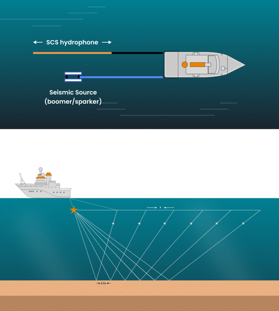
Whichever configuration is used in the survey, the acquisition sequence will be the same. A survey vessel will move along a pre-defined survey line, towing the seismic source and hydrophone behind the vessel and periodically firing the source.
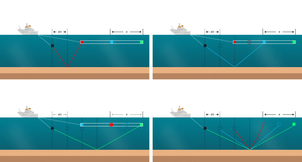
The geometry of reflectivity survey means that each time the source is fired, the hydrophone samples the seabed and subsurface reflections from a location halfway between source and hydrophone over an area half the size of the SCS array length.
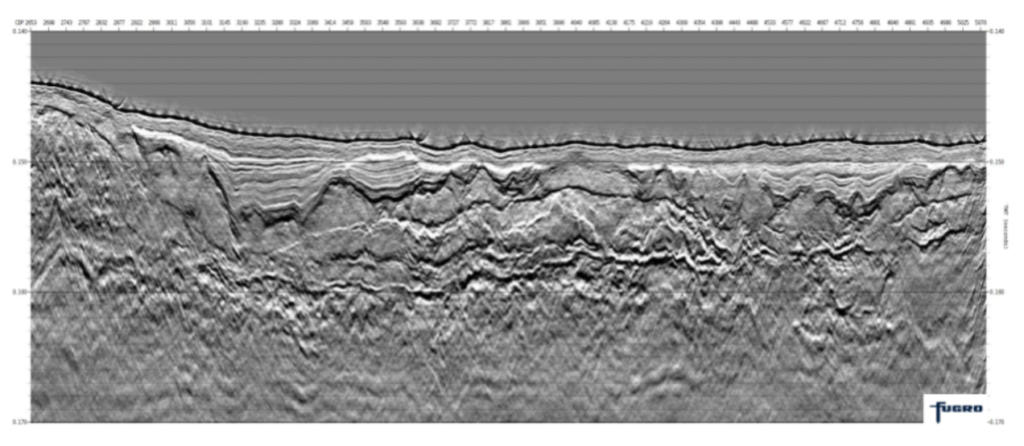
Once a survey line has been completed the data recorded at each shot location can be plotted together to produce a seismic profile.
Compared to a MCS, the geometry and mode of acquisition of SCS is very simple, comparatively cheap and can provide good sub-surface profiles with very little need for data processing and technical know-how. For this reason a SCS survey makes a great choice for ‘first pass’ surveys in new areas where little is known about the seabed and geology below. The knowledge gained from this first pass survey can then be used to focus further geophysical or geotechnical surveys that may be needed, keeping costs to a minimum.
Multi-Channel Survey (MCS) overview
With a MCS survey, although the method of data acquisition is identical to a SCS survey, the way in which data recorded from each hydrophone, then subsequently processed is crucially different.
With a multi-channel streamer the electrical response of individual hydrophone elements OR small groups of elements are recorded separately and each separate recording is referred to as a channel; hence ‘multi-channel streamer’. A multi-channel streamer will typically be far longer than a single channel streamer and have its channels evenly spaced out along its length. For high-resolution MCS surveys, streamers with 16-96 channels, and intervals of 1m, 1.56m and 3.125m are common.
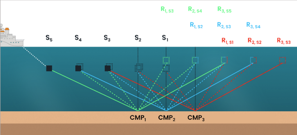
As discussed in the previous section, for every shot in a seismic survey we are sampling reflected seismic data from a ‘mid-point’ halfway between the source location (Sx) and the element/channel location (Rx). The key objective of a MCS survey is to acquire the data in such a way that each channel of the streamer records a different shot on the survey line, with a shared ‘common mid-point’ (CMP). In practice, this is done by firing the seismic source at an interval corresponding to half the channel spacing. The figure below shows visually how this works.
The geometry of a MCS gives it a number of advantages over SCS:
Improved data quality:
Signal to noise ratio is improved because, not only are recordings from different receivers combined, but also different shots.
More channels are possible: for a single channel survey the maximum length of the array is limited by water depth (shallow water requires shorter arrays). However, with the multi-channel set-up this is not the case and the array length and number of channels are not limited.
Improved data accuracy:
For both the SCS and MCS, the CMP location will have a footprint equal to half the length of the array. In SCS arrays are typically a few meters long. However, for a MCS array lengths can be much shorter; down to a few centimetres where the channel group is made up of a single element.
More processing options and a larger weather window:
Processing and enhancement of seismic data is possible through a wide range of well-established and highly developed software packages and processing companies. Although processing methods can be applied to both SCS and MCS, MCS data provided far more enhancement options. Advanced MCS data processing can lead to significant improvement in data recorded even in poor weather conditions, reducing survey operation times.
Capacity to acquire 3D data:
Multi-channel data can be acquired using multiple, simultaneously deployed, parallel streamers and sources. This gives the option to produce highly detailed 3D volumes (models) of the subsurface, rather than 2D slices.
Although these 3D volumes offer a great improvement in survey coverage and detail, they also require a larger investment in terms of equipment, expertise and processing know-how.
What are the applications of Multi-Channel Survey?
Sparker/Boomer source MCS can provide highly accurate, high-resolution data for the first 100m or so below the seabed, providing geoscientists and engineers with a valuable tool to understand local geology or to identify potential geohazards. This data is essential for offshore projects such as wind farms, where the knowledge is needed to safely carry out pylon installations and cable trenching operations.
Choosing aae equipment and our range
applied acoustics has a large range of sub-bottom profiling and seismic equipment Sparkers, CSP Units, Hydrophones and MiniPods.
We are now pleased to announce the launch of HydraSeis: our first multi-channel seismic acquisition system, designed to complement our existing range of UHR sound source and provide a step change in performance and data quality.
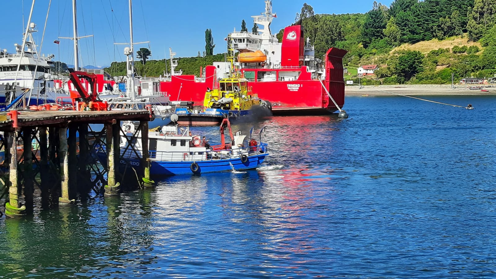
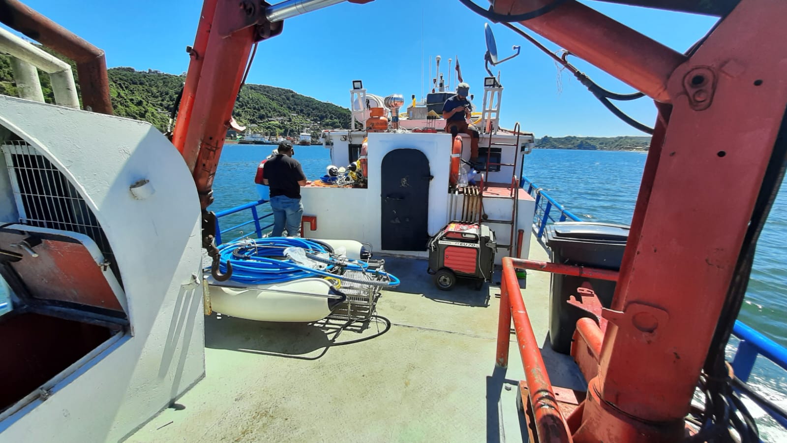
High-specification sparker systems for Sub-Bottom Profiling are fast becoming the go-to for advanced geophysical marine projects. But as technology progresses, additional training can be useful to ensure that our clients get the most from their investments. When our partners at Ocean Scan Chile required on-site training and testing, we were pleased to deploy our Geophysical Product Manager, Mike Calvert.
As you can see, Mike and the team had a very hands-on session, setting up the equipment and heading out to run survey lines and gather data.
Why the Dura-Spark UHD 400 for Ocean Scan Chile?
The Dura- Spark and CSP energy source will accompany Ocean Scan Chile in a series of advanced marine geophysics study projects that the company has been awarded. One such project is the geotechnical drilling studies and marine geophysics required to the stratigraphic characterisation of the seabed that will make it possible to define the design and engineering criteria for the breakwater extension project of the Antofagasta Port, Chile.
About the project
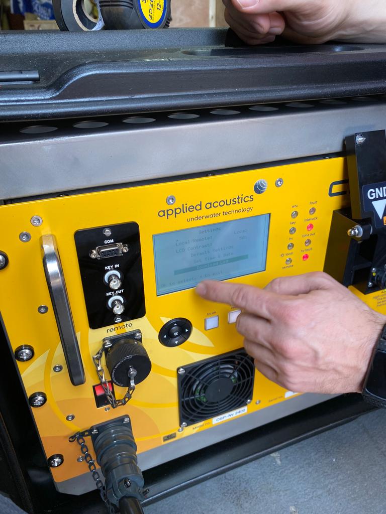
The system consists of a high power sound source – the Dura-Spark UHD 240/400 and CSP-Nv seismic energy source. Together this creates a sub-bottom profiling system that will enable Ocean Scan Chile to carry out ultra-high resolution geophysical surveys, particularly in the field of oil & gas and renewables.
Benefits of the Dura-Spark UHD 400
The Dura-Spark UHD 400 provides a lightweight, stable and repeatable sound source for sub-bottom geophysical surveys. The long-life, durable electrodes produce a consistent pulse signature and keep operational maintenance to a minimum. This provides increased survey efficiency and equipment reliability as the sparker tips rarely need replacement.
Ocean Scan Chile said…
“The arrival of this new system further modernises our company, adding state-of-the-art technology for the development of advanced studies of marine geophysics. The training session was very well received and we now feel fully competent in using the system.”

An extra layer of support when you need it
From operation and fault finding to servicing and maintenance: our specialists can deliver training remotely, at our UK HQ, or at your site or vessel. For more information about any of the products mentioned above, or to enquire about training, please contact the aae team.
Whether you’re an energy company looking to survey an offshore wind farm construction site or a telecoms company identifying safe routes for new marine cable installations, sub-bottom profiling is an essential part of a project’s safe design and completion.
But what is sub-bottom profiling and how does it work?
What is Sub-Bottom Profiling?
Sub-Bottom Profiling systems essentially work in a similar way to sonar, radar and other reflective positioning systems. They utilise an acoustic or seismic energy source, to trigger a pressure wave which travels down through the water column and into the seabed. By recording the reflected returns of this sound using a pressure sensitive hydrophone array, it is possible to build a picture of the subsurface structure and geology beneath the seabed.
There are a variety of different sub-bottom profiling systems available, some transmitting very high frequencies capable of identifying small geological features in the shallow part of the seabed (less then 10m below seabed) and some transmitting lower frequencies capable of identifying deeper geology and features (large features at 100m or more).
[Note: although lower frequencies can identify deeper geology and features, there is a trade-off in ‘resolution’. High frequencies = high resolution, shallow imaging. Low frequencies = low resolution, deep imaging.]
Types of Sub-Bottom Profiler:
SBP sound sources come in four main types, each suited to different survey environments and survey objectives:
- Pinger — The highest-frequency system (operating between 2 and 20 kHz). Uses a ceramic transducer to produce and detect acoustic pulses. Produces a high-resolution image capable of resolving small features. However, it cannot penetrate very deep into the seabed (10s of meters, depending on sediment type and water depth).
- Chirp — Another high-frequency system used for high resolution, shallow penetration surveys (usually 20-50m depending on sediment type and water depth). Chirps produce a long (low frequency) pulse, made up of multiple higher frequency waveforms. This increases the overall energy that can be output by the source, improving penetration.
- Boomer — A lower-frequency system (dominant frequencies between 500 Hz and 5 kHz) capable of penetrating much further beneath the seafloor (up to 100m). Uses an induction coil and metal plate to produce acoustic pulse. Can use a single plate or a triple plate system. The combined energy output by the triple plate system is advantageous in deeper water survey settings (up to 1000m). Capable of producing high resolution data in the 10s of cm range (depending on sediment type and water depth)
- Sparker — works by producing an electrical spark, which vaporises the sea water around the tip of the sparker array. This vaporised water rapidly expands producing a pressure wave. Large very high-powered (~12,000kJ) sparkers can produce lower frequency (down to 50Hz) and penetrate down to 1000m. Smaller sparker systems are typically employed for high-resolution sub-bottom surveys have frequency ranges comparable to that of a boomer. These often achieve penetration in excess of 100m and resolution as good as 15cm (depending on geology and survey setting).
Note: Boomers and Sparkers are usually mounted and towed on their own catamaran with a hydrophone array towed separately.
Data uses:
The data recorded by sub-bottom profilers can be used for many different purposes, including:
- Geohazard assessment for drilling or construction projects
- Planning geotechnical surveys
- Cable route surveys
- Imaging subsurface structures, geo-model building
- Identifying corals and marine habitats
- Environmental monitoring and management
- Offshore aggregate mining/monitoring surveys
Sub-Bottom Profiling System?
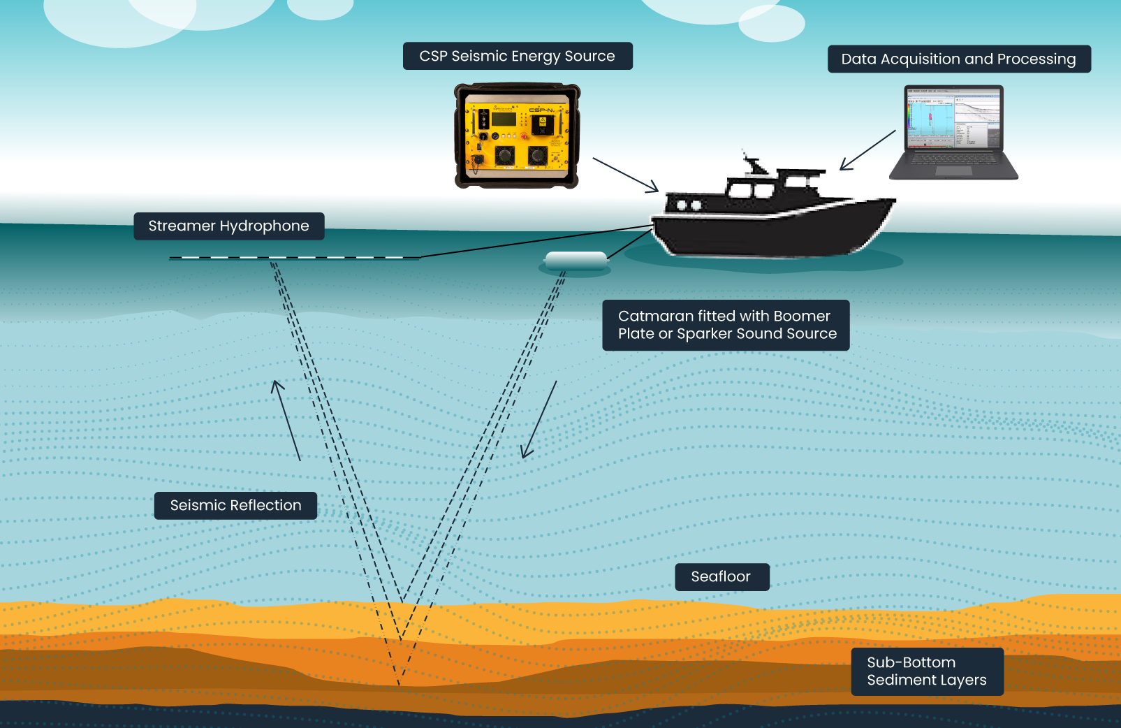
Boomer and Sparker sub-bottom profiling systems consist of four main component parts:
- Source: generates the seismic pulse
- Source power supply: provides HV electrical power for source. A small unit portable unit housing a bank of capacitors, that can be rapidly discharged to the source.
- HV cable: linking source to power suppy
- Hydrophone: Single channel (SCS) or Multi-channel (MCS) streamer (hydrophone array), for detecting seismic reflections.
- Data acquisition and processing software: for digitally recording and processing seismic data detected by hydrophone. Used to remove background noise from data and produce 2D profiles and charts.
Sub-Bottom Profiling Range
Here at aae technologies, we provide a range of industry-leading sub-bottom profiling equipment.
Boomer Systems
- AA251 — The best choice for inshore surveys and sediment analysis from smaller vessels.
- AA301 — Offers greater penetration thanks to the lengthened pulse width, ideal for coastal or shallow water surveys.
- S-Boom — A high-power, high-resolution system that uses three plates to create a focused beam pattern. Best for deep water, deep penetration surveys.
Choose from our single-plate AA251 or AA301 boomer systems, or our high-power triple-plate S-Boom system.
Sparkers
We carry a range of Dura-Spark and Delta Sparker sound sources, depending on the needs of your project:
- Dura-Spark L80 — A very lightweight (32kg), low-maintenance sparker, with a stable and consistent pulse. Ideal of coastal surveys on smaller vessels.
- Dura-Spark L200 — Versatile light (47kg) 200tip sparker. Slightly larger than the L80, allowing for increased power output.
- Dura-Spark UHD 240/400 — A flexible system that can be used in water depths from 5 to 1000m, the 240/400 system is ideal for ultra-high-resolution surveys.
- Dura-Spark UHD 400+400 — A sparker system with two 400-tip decks capable of Flip–Flop and Delay-Fire modes
- Delta Sparker — The most powerful of our sparker systems, the Delta is well suited to deeper sub-bottom profiling including geohazard assessment and construction surveys.
Hydrophones
All our SBP systems use streamer hydrophones with a flexible range of elements (1, 8, 12, or 20) for medium and low-frequency use. Our hydrophones are filled with silicon oil for neutral buoyancy and come with a 50m tow leader, pre-amplifier, and standard connectors.
Looking for a Solution for Sub-Bottom Profiling?
Or advice on choosing the best system for your requirements? If you want to explore the field on a deeper level or chat with us about our sub-bottom profiling product range, please feel free to get in touch today and speak to one of our expert team.